CIS 307: Logical (and physical) Clocks
Read Tanenbaum-vanSteen: 241-246, 252-261
Physical Clocks
Coordinated Universal Time (UTC) is the
standard used for time, based on an
atomic clock. There are radio stations that transmit a pulse each UTC second.
At receivers the accuracy is about 10ms, to account for errors in the transmitter and
mutability in atmospheric conditions. Some computers are with UTC receivers and they can
transmit time information on the internet to other computers.
Given a computer that has a local physical clock that has drift d (i.e., it will
have a maximum error d after one second), if we want it to have an error
betweek the clocks of two machines (i.e. the difference, called skew,
between the hardware clocks of the two systems at one instant] that is
never greater than e, we can do it by requesting a UTC time server for the correct time
every e/2d seconds (the factor 2 accounts for the fact that the drift can slow down
or speed up the local physical clock).
The Christian's Algorithm implements this idea. Here are two potential problems with this algorithm, together with their solution.
- The UTC time delivered to a computer may be smaller than the local time. We cannot reset the local time to the lower UTC since then certain times would be repeated (this
would be a big problem for logs). We deal with this by slowing appropriately the local
clock.
- The UTC time that is received is incorrect because of propagation delay in the delivery of the signal, and because of the overhead in processing the signal. Since
we know the Round Trip Time to+from the server (from the local clock), we can adjust
appropriately the received UTC time by adding to it RTT/2.
A number of other algorithms are used for computing synchronized physical clocks.
They are based on various forms of averaging between the times held by various computers and on the use of
a number of time servers. The most important time service available is based
on the Network Time Protocol (NTP) and involves a number of servers.
The are an unlimited number of uses for synchronized physical clocks and for logical clocks. Among them,
- For physical clocks: at-most-once message delivery and clock-based cache consistency,
(see Tanenbaum, pg 132)
- For logical clocks: scheduling, deadlock prevention, and
consistent checkpoints.
Logical Clocks
We would like to order the events occurring in a distributed system in such
a way as to reflect their possible causal connections. Certainly if an event
A happens before an even B, then A cannot have been caused by B. In this
situation we cannot say that A is the direct cause of B,
but we cannot exclude that A might have influenced B.
We want to characterize this "happened-before" relation on
events. We will consider only two kinds of events, the sending of a message
and the receiving of a message.
- If events e1 and e2 occur in the same system and e1 occurs before e2 (there
is no problem to determine this in a single system) then
e1 happened-before e2, written e1 -> e2
- If event e1 is the sending of a message and e2 is the receiving of that
message, then e1 happened-before e2
- If e1 -> e2 and e2 -> e3 then e1 -> e3
The -> relation is a partial order. Given events e1 and e2
it is not true that either they are the same event or one happened-before the other.
These events may be unrelated.
Events that are not ordered by happened-before are said to be
concurrent.
This characterization of happened-before is unsatisfactory since, given two
events, it is not immediate (think of the time it takes to evaluate a
transitive relation) to determine if one event happened before the other
or if they are concurrent. We would like a clock C that applied to an
event returns a number so that the following holds:
(1) If e1 -> e2 then C(e1) < C(e2)
We can define one such C, a logical clock (due to Lamport), as
follows:
- On each computer i we start with a clock Li set at 0
- If e is the sending of a message, then increment the local clock Li,
set C(e) to Li and timestamp the message with Li
- If e is the receiving at node i of a message with timestamp t, then set
the local clock and C(e) to max{t, Li}+1
[We could have started the local clocks with their values set
to the same value greater or equal to 0
and using as increments, instead of 1, any value greater than 0. The
resulting time still would satisfy (1)]
Here is an example showing events a,b,c,d,e,f,g,h,i,j and the corresponding
local clocks:
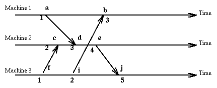
Since the method we have chosen allows different events (on different machines)
to have the same logical clock value, we extend the clock value with a number
representing the machine where the event occurred [i, C(e)] and order these
pairs according to the rule:
[i,C(e1)] < [j,C(e2)] iff C(e1) < C(e2) or [C(e1)=C(e2) and i<j]
Here is an example showing the same events but now tagged with numbers that
totally order them:
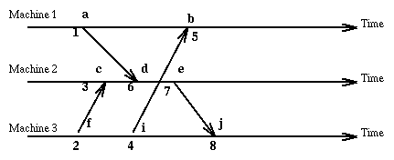
Now that events are totally ordered, we could, for instance,
maintain separate logs at each system, and then later combine the
logs in a unique way. Also, we can use these timestamps to totally
ordering multicast messages (i.e. all systems receive the multicasts in
the same order) as we will see later.
A problem of the logical clocks considered above is that they do not represent
faithfully the happened-before relation. Namely, while it is true that (1) holds,
it is not true that
(2) If C(e1) < C(e2) then e1 -> e2
It would be nice to have logical clocks that would allow us to answer
precisely questions of concurrency and dependency. We can do it by using
clock values that are vectors of numbers, one for each computer system
and then comparing vector values v and u with the rule
u < v iff ((for all components i, u[i]is less or equal to v[i]) and
(there is a j such u[j]<v[j]))
Here are the rules on vector clocks in a system with n computers:
- Each computer starts with a local clock set at [0,0,..,0]
- When on computer i there is a sending event, increment the ith component
of the clock by 1 leaving other components unchanged, then tag both the event
and the message with this value
- When on computer i there is a receiving event,
form a new local clock value taking the componentwise maximum of the local
clock and the time stamp on the arriving message. Increment the ith component by 1.
Finally tag the event with this value.
With these rules, in the vector clock v of an event e, V(e), at machine i, v[i] denotes the
number of events that occurred at machine i up to e included, and for j, j!=i, v[j] denotes the
number of events that occurred at machine j that are also known at machine i.
Here is our old example using vector clock values.
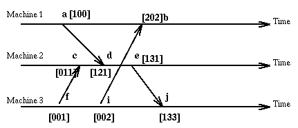
With vector clocks we have the property
e -> f if and only if V(e) < V(f)
Of course nothing is perfect. Though vector clocks allow to represent faithfully the
happened before relation between events, they result in
big time stamps and requires that we know in advance the number and identities of the sites involved.
Vector clocks can be totally ordered by ordering events with
concurrent vector clocks on the basis of the machine where they occur.
All logical clocks, whether scalar or vector, suffer of a basic problem:
though they represent that an even occurred (or not) before another, they do not
represent before by how much, that is, there is no measure of elapsed
time. In particular we cannot use logical clocks for timeouts, we need instead
a wallclock (i.e. an old fashioned clock, possibly synchronized).
Another problem of logical clocks, even vector clocks, is that they cannot account
for information exchanged outside of the computer systems, say because user A at system 1
receives output from the system and says that information to user B at system 2. And now user B
enters that information at system 2.
Messages with FIFO Property and the Causal Ordering of messages
If we send two datagrams from host n1 to host n2 using the IP or UDP protocol
we are not guaranteed that they will be received in the
order they were sent. If instead we send data using the TCP protocol we
are guaranteed that it will be received and it will be received in the order it was sent.
Let's use the following notation,
given a message m, SEND(m) is the event of sending the
message m, and RECEIVE(m) is the event of receiving the message m.
We say that a messaging system satisfies the
FIFO property if: when m1 and m2 are messages sent from the same source S
to the same destination D and we
have SEND(m1) -> SEND(m2) then RECEIVE(m1) -> RECEIVE(m2). When this
property is satisfied we have a natural ordering (total) for messages from S to D.
The FIFO property is normally used in the context of multicast messages, where we want to be sure
that messages sent from the same source are delivered everywhere in the same order.
We generalized FIFO ordering as follows:
Causal Ordering of Messages: m1 -> m2 iff (SEND(m1) -> SEND(m2)) implies !(RECEIVE(m2) ->
RECEIVE(m1))
In going from the FIFO to the causal ordering we have dropped the
requirement that messages come from the same source and that the receptions are related.
Note that the situation shown below in the diagram (A)
is forbidden in a messaging system with the FIFO property,
and the situation in diagram (B) is forbidden in a messaging system
with the causal property, while the situation in diagram (C) is a causal ordering.
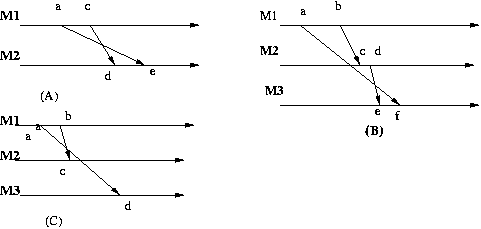
TCP assures the FIFO property on a single connection, but does not guaranty the causal property
across multiple connections. Diagram (B) above is quite possible when using TCP.
Here is another time diagram, which we call the lost client diagram.
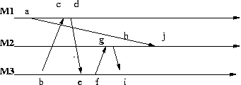
Interpret the message m1 = (a,j) to mean "Give responsibility for client x to machine M2"
Interpret the message m2 = (b,c) to mean "Who is responsible for x?"
Interpret the message m3 = (d,e) to mean "Machine M2 is responsible for x"
Interpret the message m4 = (f,g) to mean "Connect me to x"
Interpret the message m5 = (h,i) to mean "I don't know x"
Thus at i machine M3 is in a state of confusion about the whereabouts of x.
This is clearly an undesirable situation.
Here are the vector clocks for the various events:
a = [1,0,0]	b = [0,0,1]	c = [2,0,1]	d = [3,0,1]	e = [3,0,2]
f = [3,0,3]	g = [3,1,3]	h = [3,2,3]	i = [3,2,4]	j = [3,3,3]
The lost client diagram does not satisfy the causal property:
though a = SEND(m1) -> d = SEND(m3) we have e = RECEIVE(m3) -> j = RECEIVE(m1).
Making a multicast messaging system satisfy the causal property
Algorithms are available for converting a multicast messaging system
without the causal property into one where the property is satisfied.
One proceeds as follows.
The vector clock is computed to take into account only the sending of messages, not their reception
(i.e. the local component of the vector clock is not incremented when a message is received).
Thus a vector clock V on machine k will indicate at position k the number of messages sent by
machine k, and at every other position j it will indicate the highest message received
at k from j.
When node k with local vector clock v receives from node j a message m
with vector timestamp u then the message will be delivered to the application when the
following Delivery Rule holds:
- u[j] = v[j]+1, i.e. this message represents the first event at
j occurring after the last j event known at k. The local clock v is update at position j
to u[j].
- For all i != j, u[i] <= v[i], that is, node k knows now about
events at other nodes at least as
much as it was known at j when it sent the message m. v[i] is not updated.
In diagram (B) above we see that the message
at event f on machine 3 has timestamp [1,0,0] while the last event e
on machine 3 had timestamp [2,1,0]. Thus we know that the message received
at f was sent before the sending of the message received at e.
This does not help us directly since by now the message at e has been
accepted. But if we require that all messages be multicast to all
participants, then each machine
will be able to detect if a message is received out of order as shown
in the following graph
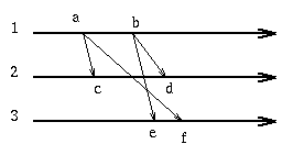
now the message at e is received with timestamp [2,0,0] while the local
clock is [0,0,0] thus we know that an event on machine 1 that
preceded the sending of this message was not received on machine 3.
Consequently we can postpone at machine 3 the delivery of the e message
until after the f event has occurred.
Causal ordering of multicast messages guaranties that messages sent by the same system will be
delivered everywhere in the same order they were sent. More in general if SEND(m1) -> SEND(m2)
then m1 will be delivered everywhere before m2. But if SEND(m1) and SEND(m2) are concurrent,
then there is no constraint on how these messages are delivered, so in one system m1 may
arrive first, in another m2 may arrive first.
Here is an example from the textbook: A database with information on bank accounts is replicated in
SF and NY. A teller in SF adds $100 to an account currently with $1000. A teller in NY simultaneously
increases that account with a 1% interest. Depending on the order these updates are done the result
is $1110 or $1111. [So NY may have $1110 and LA $1111 or viceversa. And both results will
satisfy the Causal Ordering constraint.] Certainly
we cannot live with a system where the updates can be done in different
order at the replicated sites. The problem can be solved with totally ordered
multicast: messages are delivered to all sites and delivery order is guaranteed to be the
same at all sites.
Totally ordered multicasts can be implemented as follows: each site is connected to all others with
1-1 links. Each link has two properties: 1) it is reliable 2) messages are delivered in the order
they were sent (FIFO property) . For instance TCP connections have these properties.
[Alternatively the sites may use a form of multicast that satisfies those same two
properties.]
The sites use
totally ordered logical clocks (say, vector + machine order to break ties). The sites keep queues.
- Each message, time stamped, is sent to all sites (multicast), including self.
- When a message is received, an acknowledgement is sent, time stamped with the same time
as the message, to all sites, including
self, and the message is placed in the local queue.
- A message that is in the queue and has been acknowledged by all the sites is said to be
ready. Ready messages are extracted from the queue when not later that any
non-ready message in the queue. They are then applied in the order of their
clocks.
Does this algorithm work? Let's first observe that when a message m becomes ready at a site S,
m has been received by all the sites since they have given an acknowledgement for m that was
received at S. Second, if n is
a message originated from the same site as m and sent before m, then everywhere n is received before
m and the
acknowledgements for n are received everywhere before the acknowledgements for m (this is so
because of the
properties assumed for links) thus n will be be ready before m and will be delivered to the
application (be
extracted from the queue) before m. So for each message originating site we need to worry only about
one message from that site (the other messages from that site will be naturally delayed relative to
the first one)
If message n originates from a different site than m the
argument is harder to make. It is possible that m and n are delivered in different order at
different sites. But it is certain that before making the final decision to remove from queue
either m or n, that both m and n and one acknowledgement of either m or n will be received at each
site
thus allowing the algorithm to compare clocks and possibly delay dequeueing in order to
respect the clock total order.
That is, in all cases, if n precedes m in the total order then n will become ready before m. Thus
messages are delivered to the application in their clock order.
The following diagram illustrates the situation. Machine M2 sends message m and machine M3 sends
message n. To simplify the diagram we show only the messages delivered to M1 and M4. The
acknowledgements are indicated with a broken line and a primed name.
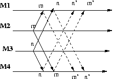
If m and n are delivered in different order at M1 and M4, m before n at M1 and n before m at M4,
then the delivery of m' at M1 will follow the delivery of n' at M1. If n follows m in the total order
of messages, then n will be delayed because will know about m. Similarly when m becomes ready at M4
it will know about n and will be delayed if it follows n in the total order of messages.
In the specific ordering displayed above, at M1 n will be delayed when n' is received until m'
is received, at which point both m and m are ready and m will be acted on before n. At M4
instead when m' is received it
becomes ready and can be applied.
In conclusion messages are applied everywhere in the order established by their totally ordered
vector clocks.
You may find interesting to see in the following diagram
all the messages generated for a single message m originated at M2.
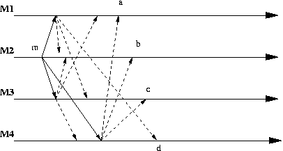
The message m becomes ready at M1, .., M4 respectively at a, .., d.
Notice that if there are n agents for each original message we will need
n-1 multicast messages
or (n-1)*(n-1) point to point messages!
We can achieve the same effect of delivering multicast messages in the
same order at all sites at the price of using a centralized controller.
Now all updates are sent to a single controller, then that controller
sends multicasts to all replicated sites. Of course this requires again
that communication channels are reliable and with the FIFO property.
Consistent Cuts
Important is also the concept of Consistent Cut, that is a cut
across the timelines of the computers in the distributed system, such that there
is no event a at computer i that is after the cut, and event b at
computer j that is before the cut, yet a happened-before b.
For example in the diagram below, the first, second, and third cuts are
consistent, while the fourth is not.
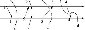
Thus in a consistent cut we forbid the situation where we see an effect (the arrival of a message)
without seeing its cause (the sending of the message).
Note that in a consistent cut it is possible to have the sending of a message
before a cut, but the receiving of that message after the cut. That means that
when considering consistent cuts we have also to worry about and save the
'in transit' messages, i.e. messages sent before the cut but received after the cut.
A consistent cut corresponds to a state
in the distributed system which can be explained on the basis of the events that
occurred up to that time, there is no evidence in one system of something
caused in another system, and the cause has not yet been seen. This is necessary for
reasonable debugging and for all situations where we want to be able
to observe the evolution of the state of a distributed system. And, most
importantly, to create checkpoints for distributed computations.
If in a transaction we transfer $100 from account A
to account B, there is a time when the $100 are out of A but not yet
in B (or viceversa). The money is like "in transit", or, this is the
preferred term, "in the [communication] channel". When we look for
consistent cuts (or states), we look for situations where either
nothing is in the channel, or where we know what is in the channel.
Chandy and Lamport have an algorithm for computing consistent global
states (also called snapshots).
- A system decided to start a
snapshot: it saves its state and sends a Marker out through its outgoing
links. It will also save the messages it receives on an in link until it receives a marker on
that link.
- When a system receives a marker for the first time, it saves its
state and sends the marker out through its outgoing links. It will also
save the messages it receives on an in link until it receives a marker on
that link.
- The algorithm terminates when each node has received markers
through all its in links. The global state consists of the state saved at the
nodes plus the messages stored by the nodes.
The Chandy-Lamport algorithm allows each node in a distributed system to
collect locally information in a way that guaranties that the totality of
the information collected represents a consistent global state. But it
does not say how to deliver to each (or some) node this total information.
This is the Global State Collection Problem.
It has the following solution:
   int i; // The identity of the current node
   State s[i]; // The information collected at node i in Chandy-Lamport
   Set V[i]; // initially V[i] = {s[i]}; It is the info collected at i
   Set W[i]; // initially W[i] is empty; It is the info sent from i

   while (!terminationCondition) {
      if (V[i] != W[i]) then send V[i]-W[i] on all outgoing arcs
      if (arc from j to i contains message M) then V[i] = V[i] union M
   }

   Terminate when V[i]==W[i] for all i and all arcs from any i to any j
   are empty. But how can we determine if these conditions are true?
   We need a termination detection algorithm.
   One such algorithm is the Dijkstra-Scholten algorithm.
And here is the Dijkstra-Scholten Termination Detection Algorithm
At each node k (we assume that k=0 is the node that starts the algorithm and it has no predecessor) it is run the
following algorithm:
	Variables:
		C: integer; // Represents the number of messages received by node
			    // and not acknowledged
		D: integer; // Represents the number of messages sent by node
			    // and not acknowledged
		M: {signal, ack}; // value of a message sent on a link
		sender: integer; // The sender of a message
		parent: integer; // The identity of a node - used to build a
			    // spanning tree
	begin
		C = D = 0;
		parent = k;
		if (k == 0) {
		    c = 1;
		    for each successor {
			send signal message to that successor;
			D++;
		    }
		}
		while (true) {
		    if (there is a message on a link) {
			set M to the message and sender to its sender;
			if (M == signal) {
			    if (C == 0) {
				C = 1;
				parent = sender;
				for each successor {
				    send signal message to that successor;
				    D++;
		    		}
			    } else if (C == 1) {
				send ack message to sender
			    }
			} else { // The message is an ack
			    D--;
			}
		    }
		    if (C == 1 && D == 0) {
			send ack to parent;
			C = 0;
			parent = k;
			if (k == 0)
			    The algorithm has terminated
		    }
		}
	end
Here is an example:
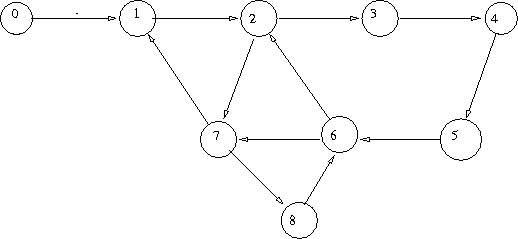
We show a possible evolution of the algorithm. In the following table we state for each node the value
of the parent, C, and D
| 0 | 1 | 2 | 3 | 4 | 5 | 6 | 7 | 8 |
|---|
| 0,0,0 | 1,0,0 | 2,0,0 | 3,0,0 | 4,0,0 | 5,0,0 | 6,0,0 |
7,0,0 | 8,0.0 |
| 0,1,1 | 1,0,0 | 2,0,0 | 3,0,0 | 4,0,0 | 5,0,0 | 6,0,0 |
7,0,0 | 8,0.0 |
| 0,1,1 | 0,1,1 | 2,0,0 | 3,0,0 | 4,0,0 | 5,0,0 | 6,0,0 |
7,0,0 | 8,0.0 |
| 0,1,1 | 0,1,1 | 1,1,2 | 3,0,0 | 4,0,0 | 5,0,0 | 6,0,0 |
7,0,0 | 8,0.0 |
| 0,1,1 | 0,1,1 | 1,1,2 | 2,1,1 | 4,0,0 | 5,0,0 | 6,0,0 |
2,1,2 | 8,0.0 |
| 0,1,1 | 0,1,1 | 1,1,2 | 2,1,1 | 3,1,1 | 5,0,0 | 6,0,0 |
2,1,1 | 7,1,1 |
| 0,1,1 | 0,1,1 | 1,1,2 | 2,1,1 | 3,1,1 | 4,1,1 | 8,1,2 |
2,1,1 | 7,1,1 |
| 0,1,1 | 0,1,1 | 1,1,2 | 2,1,1 | 3,1,1 | 5,0,0 | 6,0,0 |
2,1,1 | 7,1,0 |
| 0,1,1 | 0,1,1 | 1,1,2 | 2,1,1 | 4,0,0 | 5,0,0 | 6,0,0 |
2,1,0 | 8,0,0 |
| 0,1,1 | 0,1,1 | 1,1,0 | 3,0,0 | 4,0,0 | 5,0,0 | 6,0,0 |
7,0,0 | 8,0,0 |
| 0,1,1 | 0,1,0 | 2,0,0 | 3,0,0 | 4,0,0 | 5,0,0 | 6,0,0 |
7,0,0 | 8,0,0 |
| 0,1,0 | 1,0,0 | 2,0,0 | 3,0,0 | 4,0,0 | 5,0,0 | 6,0,0 |
7,0,0 | 8,0,0 |
| 0,0,0 | 1,0,0 | 2,0,0 | 3,0,0 | 4,0,0 | 5,0,0 | 6,0,0 |
7,0,0 | 8,0,0 |
If one gives up on a fully distributed approach, and allows for a
checkpoint coordinator (or two for reliability), then the complexity of
the solution is
dramatically reduced by having each node report its state and transit
messages to the coordinator(s).


