CIS307: Examples of Layers and Protocols
Data Link Layer
The data link layer transfers information reliably over the physical layer
between neighboring nodes. The connection between neighbors can be
point-to-point, i.e. a direct link, or shared, i.e. a link that is shared between a
number of nodes, as with Ethernet. In the case of shared medium
we need a MAC (Medium Access Control) protocol to regulate access
to the shared medium, like CSMA/CD used with Ethernet. Once access is
resolved (or it is unnecessary as in point-to-point), one has DLC
(Data Link Control) which carries out the main functionality of the Data
Link Layer.
A basic problem at the data link layer
is what to do when errors are detected at the receiver end.
As we have already seen we use one of the three possible forms
of Automatic Repeat Request methods, stop-and-wait,go-back-n,
selective-repeat.
In the case of stop-and-wait we have a problem: a sender sends a frame.
It is received and acknowledged. The ack is lost. The sender times out while
waiting for reply. Then it sends message again. At this point the receiver
has no way of knowing that this is the old frame and not a new one.
Solution: tag each frame with a sequence bit, that is 0, 1, 0, 1, ..
in successive distinct frames. But it remains at the current value
when a frame is resent. So we have;
SENDER:                                RECEIVER:
  int sequencebit = 0;                   int sequencebit = 0;
  frame oldframe (read it), newframe;    frame theframe;
  for (;;) {                             for (;;) {
    copy sequencebit to oldframe;          waitforframe(theframe, timeout);
    send oldframe;                         if (!timeout && sequencebit == bit in frame){
    waitforack(timeout);                     save theframe;
    if (!timeout && !NACK){                  sequencebit = (sequencebit+1)%2;
       read newframe;                        send ack;
       oldframe = newframe;                }
       sequencebit = (sequencebit+1)%2;  }
    }
  }
Notice than in the case of both Go-Back-N and of Selective-Repeat we need
a way to identify frames. To this end one uses identifiers, say n bits,
that identify a frame among the outstanding frames. So if it uses 3 bits,
we have as identifiers 0,1,2,3,4,5,6,7 and when an id has been acknowledged
it can be reused (sliding window protocol).
ARP: Address Resolution Protocol
On a LAN at the data link + physical layer frames are sent to physical addreses,
not to IP addresses.
ARP packets are broadcast to a local area network when we need to determine
the hardware address corresponding to a given IP address. The host with
that IP address will respond giving its own physical address.
The ARP packet used on ethernet has form:
    0                   1                   2                   3
    0 1 2 3 4 5 6 7 8 9 0 1 2 3 4 5 6 7 8 9 0 1 2 3 4 5 6 7 8 9 0 1
   +-+-+-+-+-+-+-+-+-+-+-+-+-+-+-+-+-+-+-+-+-+-+-+-+-+-+-+-+-+-+-+-+
   |    Hardware Address Type      |    Protocol Address Type      |
   +-+-+-+-+-+-+-+-+-+-+-+-+-+-+-+-+-+-+-+-+-+-+-+-+-+-+-+-+-+-+-+-+
   | HADDR length  | PADDR length  |          Operation            |
   +-+-+-+-+-+-+-+-+-+-+-+-+-+-+-+-+-+-+-+-+-+-+-+-+-+-+-+-+-+-+-+-+
   |                Sender HADDR (first 4 octets)                  |
   +-+-+-+-+-+-+-+-+-+-+-+-+-+-+-+-+-+-+-+-+-+-+-+-+-+-+-+-+-+-+-+-+
   |Sender HADDR (last 2 octets)   | Sender PADDR (first 2 octets) |
   +-+-+-+-+-+-+-+-+-+-+-+-+-+-+-+-+-+-+-+-+-+-+-+-+-+-+-+-+-+-+-+-+
   |Sender PADDR (last 2 octets)   | Target HADDR (first 2 octets) |
   +-+-+-+-+-+-+-+-+-+-+-+-+-+-+-+-+-+-+-+-+-+-+-+-+-+-+-+-+-+-+-+-+
   |                   Target HADDR (last 4 octets)                |
   +-+-+-+-+-+-+-+-+-+-+-+-+-+-+-+-+-+-+-+-+-+-+-+-+-+-+-+-+-+-+-+-+
   |                   Target PADDR (last 4 octets)                |
   +-+-+-+-+-+-+-+-+-+-+-+-+-+-+-+-+-+-+-+-+-+-+-+-+-+-+-+-+-+-+-+-+
To avoid the transmission of too many ARP packets a cache is used to keep
track of known pairs [IP address, Physical addres]. When an ARP packet
is received, its sender's pair is added to the cache if not already there.
Cache entries are eliminated either because of overflow or because
of aging of the pairs (entry becomes stale).
RARP (Reverse ARP) is used when a diskless station is booted on a LAN.
It sends out a packet with its own physical address and asks others to tell
him what is its IP address.
Network Layer
IP Role
IP provides an unreliable, best-effort, connectionless packet delivery
service between computer systems. It supports:
- Addressing: how to identify networks and hosts
- Routing (switching): how to move packets towards their destination
- Fragmentation: it takes care of the fact that different networks
may have different MTUs (Maximum Transfer Units), and thus they may need
to fragment an existing packet when going through a network with smaller MTU.
IP does not do directly:
- Computation of Routing Tables(done by other protocols)
- Congestion control
- Flow control
- Error control
- Resource management
IP Header
    0                   1                   2                   3
    0 1 2 3 4 5 6 7 8 9 0 1 2 3 4 5 6 7 8 9 0 1 2 3 4 5 6 7 8 9 0 1
   +-+-+-+-+-+-+-+-+-+-+-+-+-+-+-+-+-+-+-+-+-+-+-+-+-+-+-+-+-+-+-+-+
   |Version|  IHL  |Type of Service|          Total Length         |
   +-+-+-+-+-+-+-+-+-+-+-+-+-+-+-+-+-+-+-+-+-+-+-+-+-+-+-+-+-+-+-+-+
   |         Identification        |Flags|      Fragment Offset    |
   +-+-+-+-+-+-+-+-+-+-+-+-+-+-+-+-+-+-+-+-+-+-+-+-+-+-+-+-+-+-+-+-+
   |  Time to Live |    Protocol   |         Header Checksum       |
   +-+-+-+-+-+-+-+-+-+-+-+-+-+-+-+-+-+-+-+-+-+-+-+-+-+-+-+-+-+-+-+-+
   |                       Source Address                          |
   +-+-+-+-+-+-+-+-+-+-+-+-+-+-+-+-+-+-+-+-+-+-+-+-+-+-+-+-+-+-+-+-+
   |                    Destination Address                        |
   +-+-+-+-+-+-+-+-+-+-+-+-+-+-+-+-+-+-+-+-+-+-+-+-+-+-+-+-+-+-+-+-+
   |                    Options                    |    Padding    |
   +-+-+-+-+-+-+-+-+-+-+-+-+-+-+-+-+-+-+-+-+-+-+-+-+-+-+-+-+-+-+-+-+

Version: Current IP  4
         Next Generation:  6 ==> IPv6 or IPng
IHL: Header Length in words:  without options it is 5, with
         options it can be as high as 15.
Type of Service: the sender specifies the type of service desired.
	 Three bits can be used to specify the priority of the message.
	 Three bits can be used to characterize the aim, if one
         that maximizes reliability, or one that minimizes delivery
         time, or one that maximizes throughput.
Total Length: 16 bits ==> maximum packet size 65,535 Bytes (64 KB)
         including header length
Identification: unique for each IP datagram
       (1) source increments a counter
       (2) gateway copies
       All the fragments of the same packet have the same identification.
Flag: three bits, two lower bits used for fragmentation, the third is not used:
       (1) first bit if 1, means do not fragment (this is the DF flag)
       (2) second bit if 1, means more fragment are coming (not end of packet)
          (This is the MF flag.)
Fragment Offset: offset in the original datagram in units of 8 octets. All
       fragments, except the last, must be multiples of 8 octets.
TTL:   each gateway decrements TTL by some number and discard the packet if it
       reaches 0. If discarded, the sender is informed using the ICMP (Internet
       Control Message Protocol) protocol.
       In theory, it counts in second units and discards a packet that takes
       255 seconds to propagate.
Protocol: number of the higher level protocol that is using the current packet
       ICMP: 1, TCP: 6, UDP: 17
checksum: it is the one-complement of the one-complement sum of the header.
       Notice that it is the one-complement so that at the receiver no
       subtraction is required, just a comparison to zero.
Some observations on IP protocol:
- Fragments of a packet are not re-assembled together until the final
destination is reached. There, if a fragment is missing, or a fragment
is with bad data check, all the fragments are discarded.
- If necessary, a fragment may be further decomposed. All the fragments of a
packet have the same header, except for minor differences like fragment offset,
flags, checksum.
- When an IP packet arrives at a router its header checksum is computed
and, if incorrect, the packet is discarded.
ICMP: Internet Control Message Protocol
It is encapsulated within an IP packet. It is used both for requests and for responses.
It supports the at least the following message types:
- Source Quench: A router that has to discard a packet because it has run
out of buffer space sends a Source Quench message to the source of the packet.
That source will have to slow down the rate at which it sends packets.
- Time Exceeded: It is sent to the source of a packet when a router has to
discard that packet since its TTL has reached zero, or when the destination
of the packet is unable to collect all the fragments of the packet before the
time out expires.
- Destination Unreacheable: sent to source of packet when a router cannot find
its destination, either network or host.
- Fragmentation Required: when there is need of fragmentation, but fragmentation
is not allowed because the non fragmentation flag is set in the packet.
- Echo Request/Reply: When a node receives an Echo Request it is supposed to send a
Echo Reply message.
- Address Mask Request/Reply: When a host first starts, it sends an
Address Mask Request on the local network and a local router replies
with an Address Mask Reply indicating the subnet mask of the network.
- Redirect: Used by a router to say to sender the id of another
router better suited for sending messages to specified receiver.
ICMP is used to implement ping (using the EchoRequest/Reply
messages), traceroute (IP using the TimeToLive, and ICMP using the
TimeExceeded message), and to determine a
path's MTU (IP using the DF flag and ICMP using the FragmentationRequired
message). It is also used to report on errors that occur during the
transmission of IP packets.
Here is the format of its header
    0                   1                   2                   3
    0 1 2 3 4 5 6 7 8 9 0 1 2 3 4 5 6 7 8 9 0 1 2 3 4 5 6 7 8 9 0 1
   +-+-+-+-+-+-+-+-+-+-+-+-+-+-+-+-+-+-+-+-+-+-+-+-+-+-+-+-+-+-+-+-+
   |   type        |    code       |           checksum            |
   +-+-+-+-+-+-+-+-+-+-+-+-+-+-+-+-+-+-+-+-+-+-+-+-+-+-+-+-+-+-+-+-+
   |              id               |           sequence            |
   +-+-+-+-+-+-+-+-+-+-+-+-+-+-+-+-+-+-+-+-+-+-+-+-+-+-+-+-+-+-+-+-+
The type field identifies the operations with the codes shown above. The code field provides additional
information about these operations. The id and sequence fields are used in conjunction with some operation
(Echo Reply). The header may be followed by filler data. The checksum is for the whole ICMP packet.
This packet is carried within the IP packet.
Transport Layer
It supports communication between processes (not just computer systems).
UDP Header
The User Datagram Protocol is the simplest transport protocol.
It just adds multiplexing, in the form of ports, unsigned 16 bit
integers, to the IP protocol, and a simple error check, in the form
of a checksum. The checksum is computed over the whole UDP datagram
(UDP header + message) plus
four fields from the enclosing IP packet:
length+protocol+SourceAddress+DestinationAddress.
The reason for using these extra fields is the desire to detect
if in transit the source or destination of the packet have been modified
[this is not to detect a malicious router, but to detect a routing
mistake]. The checksum is computed as in the case of IP packets (one
complement of one-complement sum).
Note that the checksum will be computed only at the endpoints, not in
transit.
The messages exchanged are called datagrams,
i.e. communication is connectionless. The format of the UDP header is:
    0                   1                   2                   3
    0 1 2 3 4 5 6 7 8 9 0 1 2 3 4 5 6 7 8 9 0 1 2 3 4 5 6 7 8 9 0 1
   +-+-+-+-+-+-+-+-+-+-+-+-+-+-+-+-+-+-+-+-+-+-+-+-+-+-+-+-+-+-+-+-+
   |          source port          |        destination port       |
   +-+-+-+-+-+-+-+-+-+-+-+-+-+-+-+-+-+-+-+-+-+-+-+-+-+-+-+-+-+-+-+-+
   |         checksum              |          length               |
   +-+-+-+-+-+-+-+-+-+-+-+-+-+-+-+-+-+-+-+-+-+-+-+-+-+-+-+-+-+-+-+-+
TCP Header
The Transmission Control Protocol (TCP) is a connection oriented
[thus sender and receiver are as connected in a virtual circuit],
bidirectional [i.e. full duplex],
stream oriented [as opposite to message oriented,
i.e. users think in terms of sending and receiving a stream of
octets; the implementation will actually use messages, called segments.]
reliable transmission protocol at the transport layer.
The same format for the header is used in both directions in a
connection.
Here is a picture of the header of a segment and a description
of some of its fields.
    0                   1                   2                   3
    0 1 2 3 4 5 6 7 8 9 0 1 2 3 4 5 6 7 8 9 0 1 2 3 4 5 6 7 8 9 0 1
   +-+-+-+-+-+-+-+-+-+-+-+-+-+-+-+-+-+-+-+-+-+-+-+-+-+-+-+-+-+-+-+-+
   |          source port          |        destination port       |
   +-+-+-+-+-+-+-+-+-+-+-+-+-+-+-+-+-+-+-+-+-+-+-+-+-+-+-+-+-+-+-+-+
   |                        sequence number                        |
   +-+-+-+-+-+-+-+-+-+-+-+-+-+-+-+-+-+-+-+-+-+-+-+-+-+-+-+-+-+-+-+-+
   |                 acknowledgement number                        |
   +-+-+-+-+-+-+-+-+-+-+-+-+-+-+-+-+-+-+-+-+-+-+-+-+-+-+-+-+-+-+-+-+
   | TCP |             |U|A|P|R|S|F|                               |
   |Headr|             |R|C|S|S|Y|I|       window size             |
   |lengt|             |G|K|H|T|N|N|                               |
   +-+-+-+-+-+-+-+-+-+-+-+-+-+-+-+-+-+-+-+-+-+-+-+-+-+-+-+-+-+-+-+-+
   |       checksum                |   urgent pointer              |
   +-+-+-+-+-+-+-+-+-+-+-+-+-+-+-+-+-+-+-+-+-+-+-+-+-+-+-+-+-+-+-+-+
   |                    Options (0 or more words)                  |
   +-+-+-+-+-+-+-+-+-+-+-+-+-+-+-+-+-+-+-+-+-+-+-+-+-+-+-+-+-+-+-+-+
- Source and Destination Ports:
- They are 16 bit numbers. A port number is local to a specific
host, i.e. different hosts have
65,535 different ports.
In unix /etc/services keeps a list of
specific uses for some of these ports.
For example, HTTP uses 80, Telnet
uses 23, FTP uses 21. The first 1024 ports are said to be "well known" and
are reserved.
Notice that ports allow us to communicate
with specific programs on a computer, not just with a computer as in IP.
- Sequence and Acknowledgement Numbers:
- These numbers are local to a connection between two nodes,
they are intended to be unique during the life of a connection. The initial
sequence number is agreed between the sender and the receiver when the
connection is set up
with a Three-Way-Handshake [SYN->, SYN+ACK<-, ACK->].
For example, if two nodes A, B are communicating, then A as sender
may choose initially the number 200 (then the first data byte sent will be
200) and B as sender may choose initially the number 500.
Then B will acknowledge messages relative to 200 (say 260 = I have
received everything up to 259 included) and A will acknowledge
messages relative to 500 (say 610 = I have received everything up to
609 included, the next byte I expect is 610).
- Length of the TCP header:
- It is counted in 32-bit words.
- Flags:
- There are six flags:
- URG: It is 1 if the Urgent Pointer is used.
- PUSH: Request, on sender, that this segment should be transmitted asap,
and, on the receiver, that it be delivered asap.
- ACK: Confirms that the acknowledgement field is valid
- SYN: Request to setup a connection. It must be acknowledged.
- FIN: Request to shutdown. It must be acknowledged.
- RESET: Receiver is confused. It requests the sender to abort the
connection.
- Window Size:
- It specifies the size of the receiver's available buffer (called
window).
- Urgent pointer:
- Byte offset from the current sequence number at which urgent
data will be found.
- CheckSum:
- Defined as in UDP: it is over the whole segment plus from the IP packet
protocol+length+sourceaddress+destinationaddress.
Some of the issues dealt with at the transport level, in particular by
TCP, are:
- Message identification: Managing identifiers for messages to make sure
that stale messages (i.e. messages that are still in the network, but have
been superceded by other messages)
do not create confusion. It may use lower k bits from the local timer. One must
make sure that no two messages are sent for the same tick of the clock (that is usually
the case) and that no message remains alive across the intervening time (2^k ticks).
The transmitter and receiver both identify their messages and these identifiers
are usually different. Or it may use a sequential counter.
- Connection management, both starting and terminating a connection, and multiplexing
multiple connections.
A connection is started by a client (active open) using a
three-way handshake.
The transmitter sends ConnectionRequest(seq=x,SYN)
to start a connection with transmitter id x.
The receiver, the server that previously performed a passive open,
replies ConnectionAccepted(seq=y, SYN+ACK=x+1),
to acknowledge x (ready to accept x+1) and establish for its
messages the identity y. Finally the transmitter confirms the connection
with ConnectionAccepted(seq=x,ACK=y+1)
to confirm its own identifier x and accept the receiver's
identifier y (ready to accept y+1).
If the receiver wanted to reject x, it would send Reject(ACK=x), and if the
transmitter wanted to reject y it would send Reject(ACK=y).
As part of the handshake the
transmitter and receiver specify their MSS (Maximum Segment Size),
that is the maximum size of
a segment they can accept. A typical value for MSS is 1460.
A connection is terminated with a similar four-way handshake
[FIN->, ACK<-, FIN<-, ACK->]. For more information on these handshakes,
and a state diagram that helps you see what is going on, see the
notes on sockets.
- Error management, including error detection, error control, choosing
timeouts.
For timeouts, for each distinct destination one keeps track of round
trip times, RTT,
and chooses a timeout that is computed from the recent RTTs. One may compute
an estimated
RTT that is the exponential average of the RTTs and then choose the timeout as 2 times that
estimate. [Exponential averaging assumes a number a, 0<=a<=1, and computes a
sequence of estimated RTTs according to the formula
ERTT(i+1) = a*ERTT(i) + (1-a)*RTT(i).]
In the case of TCP a more sophisticated method is used.
It computes a timeout value using information
about the average and standard deviation of the round trip times, and does
so without need for floating point arithmetic (it uses approximations).
- Managing message fragmentation.
- Flow Control. Here we use the Sliding Window Protocol. Remember that flow control deals
with the ability of the end receiver of a transmission to deal with incoming messages.
- Congestion Control.
Remember that congestion control deals with the ability of the network to
deal with current traffic, i.e. it refers to the intermediate routers and
links, not to the endpoints of the transmission.
Congestion Collapse is what could happen when IMPs get overloaded,
run out of buffer space and start throwing away incoming segments. Then
the original sender times out and sends additional copies of the segments that
add to the traffic.
These are complex issues whose solutions go by interesting names slow
start, fast retransmit, and fast recovery.
The transmitter knows the receiver's window from the Sliding Window Protocol.
It maintains in addition a Congestion Window and a Threshold,
initially 64KB. The amount of data that can be transmitted is the minimum of
the sliding window and the congestion window.
The congestion window starts at the maximum size of a segment.
If a message is acknowledged, the congestion window is incremented
by one segment, and so on until
the threshold is reached or a message is lost due to congestion. When the
threshold is reached, the congestion window can still grow, but now
it is incremented
by a single maximal segment per round-trip time.
When a message is
lost, the threshold is set to 1/2 of the congestion window and the congestion
window is restarted at the size of the maximum segment. [Of course you
may wonder how the sender knows that a segment is lost - for example by
timeout, or double-acknowledgement for the start byte of the lost segment.]
Another technique for dealing for congestion: we are in the case where
small data messages are being send, say, single characters in a telnet
session. The Nagle Algorithm deals with this situation: the user
types at some speed. The first character is sent immediately. The others
are accumulated and sent together when either ACK comes back from receiver,
or 500ms have elapsed. A symmetric arrangement can be made in receiver
publicizing that the available window not when it transitions from 0 to 1 but
to a larger number (like half the buffer size).
An interesting result for the congestion control algorithm is
that the data rate it supports is proportional to MSS, the average size of the segments,
inversely proportional to RTT, the round-trip time, and proportional to
the square root of n, the average number of segments delivered before one is lost.
Application Layer
Domain Name System (DNS)
Pages 201..206 in Tannenbaum-VanStein.
The DNS is a distributed system whose primary purpose is to map between
domain names and IP addresses.
The domain name space is a rooted tree where a path is a
domain name. A subtree is a domain.
Each link is labeled (with up to 63 alphanumeric characters). The labels in
a path are separated by '.' and the root is '.' (usually not written out).
A domain name, left to right,
gives a path to the root. The total length of a domain name is at most 255 characters.
The domain name space is partitioned in non
overlapping zones. Each zone has a primary
name server and a secondary name server.
The primary name server is said to be an authoritative
name server in that it is the supreme authority for the mapping
domain name/IP address for the zone. It maintains information about its zone in
persistent memory.
Every host must be registered with
an authoritative server and know the identity of that server
(and of the secondary name server, and possibly of a tertiary name server).
Root name servers are
the name servers associated to the nodes immediately below the root '.'.
That is, things like "com", "edu", etc.
Local name servers are
the remaining servers, located within our organizations.
The fact that the DNS name space is hierarchical, and the zones form
a partition is confusing. Temple.edu is a domain containing cis.temple.edu.
If temple.edu represents a zone, then temple will not contain any other
zones and the primary name server of temple.edu will be authoritative for the
whole of Temple. However, if cis.temple.edu is defined as a zone,
then temple.edu will be partitioned into zones and when the name server
of temple.edu is requested for the IP address of joda.cis.temple.edu,
if it does not have that information in its cache, will have to send the
request to the authoritative name server of cis.temple.edu.
Each node holds a set of resource records (RR) of different
types (SOA, A, MX, SRV, NS, CNAME, PTR, HINFO, TXT, LOC)
that are associated to various entities (Host, Domain, Zone).
Each node represents a host, or a domain, or a domain+zone.
The primary name server keeps a data base with information about all
the nodes in its zone. The secondary name server gets copies of this data base
by requesting zone transfers.
A node may have many names, a canonical name and aliases, and it can have
multiple IP addresses if it is multi-homed. An IP address may be associated
to more than one node, in which case routers will have to choose based on
some priority where to route to (they may perform a round-robin changing the
priorities of the alternatives).
Resource records have a class (we are only interested in the internet
class IN), a type, an associated entity, a value, and a time-to-live
(which we neglect to discuss).
Some resource record types are:
- A: An Address record. It is associated to a host and has
as value an IP address. For example
joda.cis.temple.edu. A 155.247.71.60
ns1.temple.edu. A 155.247.166.2
These are the means for mapping domain names to IP addresses.
- NS: A Name Server record. Each zone must have at
least one NS record, but hosts could also have them.
It is associated to a zone (host)
and has as value the domain name of a name server for that zone (host).
For example
joda.cis.temple.edu. NS ns1.temple.edu.
states that ns1 is the primary name server for joda.cis.temple.edu.
- CNAME: A Canonical Name record. It is associated to
a host name that is an alias for a "canonical" host name. For example:
www.cis.temple.edu. CNAME joda.cis.temple.edu.
- SOA: A Start of Authority record. It is associated to a
zone and specifies things like the authoritative name server for this
zone, the email address of the person managing the zone, the time interval
for refreshing the zone, the time-to-live for resource records exported
from the zone, etc. For example:
    cs.vu.nl. SOA
	postmaster.cs.vu.nl(  ; contact email is postmaster@cs.vu.nl
	27183,		     ; serial number (increased when file is revisioned
	7200,		     ; refresh time (2 hrs) when to check with primary
			     ; zone authority for changes
	3600,		     ; retry time (1 hr), time to retry a failed zone
			     ; transfer
	86400,		     ; expire time (1 day), maximum time for zone update.
			     ; If surpassed, the secondary zone server will
			     ; stop answering queries
	3600)		     ; Minimum TTL (1 hr), supplied by primary zone authority
			     ; to secondary to indicate upper limit for keeping a
			     ; record in the cache
- MX: A Mail eXchange record. It specifies for a
mail address the host name of its mail server. For a given mail address
there may be multiple MX records. A priority is associated to each record.
For example:
cis.temple.edu. MX 0 falcon.cis.temple.edu.
cis.temple.edu. MX 10 joda.cis.temple.edu.
Here falcon would have priority on joda. A mail server that received
a request for ingargiola@cis.temple.edu would use the MX records to obtain
the name falcon.cis.temple.edu, and then would look for an A record for
falcon.cis.temple.edu to obtain its IP address.
- SRV: A Service record. It is associated to a domain and
specifies a server for a service. For example:
_http._tcp.cis.temple.edu SRV 10 4 80 joda.cis.temple.edu
which specifies where to direct HTTP requests. Notice the 10: it has the
same meaning as the priority for MX records (thus we can have multiple
service records). Notice the 4: it specifies, at the same priority, the
proportion of requests to direct to this server (load balancing).
Notice the 80: the port where the service is available.
- PTR: A Pointer record. It is associated to a host and
has as value the domain name of that host. It is used for example to implement an
inverse name lookup, from IP address to host name. For example:
to obtain for the IP address 155.247.71.60 the host name joda.cis.temple.edu
we create the PTR record
60.71.247.155.in-addr.arpa. PTR joda.cis.temple.edu.
The DNS protocol uses the information available in the DNS
data bases. This protocol uses UDP packets on port 53
with the same format for both requests and responses:
  +-----------+
  | header    |
  +-----------+
  | question  | an RR type and a domain name
  +-----------+
  | answers   | the RRs that match the request
  +-----------+
  | authority | NS records pointing to name servers
  +-----------+
  | additional| other RRs that may be useful to requestor
  +-----------+
The DNS system is implemented on regular hosts that are at
the edges of the internet. They are not, contrary to routers
and switches, part of the inner fabric of the internet. Thus DNS
respects the End-To-End Principle.
HTTP: Hypertext Transfer Protocol
In the HTTP protocol a client sends a request
to a server and receives a response.
The HTTP messages being exchanged have the following format:
HTTPMessage ::=
	Header
	crlf		; CarriageReturn LineFeed
	EntityBody

Header ::= RequestHeader | ResponseHeader

RequestHeader ::=
	RequestLine
	Generalheaders
	RequestHeaders
	EntityHeaders

ResponseHeader ::=
	StatusLine
	GeneralHeaders
	ResponseHeaders
	EntityHeaders

RequestLine ::= command .. ; where command is GET or HEAD or POST or PUT
			   ; or TRACE or DELETE

StatusLine ::= HTTP-version status .. ; where status is a number n, 100 <= n < 200,
			 ; informational (request received, continuing processing)
			 ; 200 <= n < 300, meaning success, or 300 <= n < 400, meaning
			 ; redirect, or 400 <= n < 500, meaning client error, or
			 ; 500 <= n < 600 meaning server error.

GeneralHeader	; For example:
		; Date: Tue, 15Nov 1994 08:12:31 GMT
		; Connection: close

RequestHeader	; For example:
		; Accept: text/plain
		; User-Agent:
		; Referer: http://www.w3.org/hypertext/DataSources/Overview.html

ResponseHeader	; For example:
		; Server: CERN/3.0 libwww/2.17
		; Retry-After: 120

EntityHeader	; ForExample:
		; Content-Type: text/html
		; Content-Length: 1284
		; Content-Encoding: gzip
		; Last-Modified: Tue, 15 Nov 1994 12:45:26 GMT
HTTP version 1.0 (the original version) was enhanced in version 1.1
by adding persistent connections and pipeling as described in the following diagram:
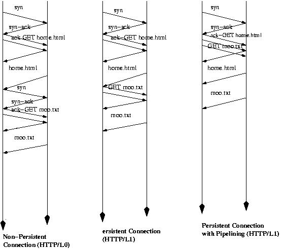
The saving from each diagram to the next is one round-trip time per
request.
The Common Gateway Interface, CGI, is[was] used for generating dynamically pages on the server.
The pages are generated by invoking appeopriate programs.
For example http://www.who.com/cgi-bin/foo?32&33
asks the server to execute the program foo passing to it the parameters 32 and 33.
ingargio@joda.cis.temple.edu