 CIS 307: Introduction to Distributed Systems I
 [SISD,SIMD,MISD,MIMD],
[Computational Speedup],
[Some Characteristics of Communication Primitives],
[Network OS vs Distributed OS],
[OSI Architecture],
[TCP/IP Architecture],
[Internet Addresses],
[Information in the IP Header],
[Information in TCP Header],
[Sliding Window Algorithm],
[Ethernet],
[More Readings on TCP/IP Architecture],
[Client-Server Architecture],
[Intranets]
[SISD,SIMD,MISD,MIMD],
[Computational Speedup],
[Some Characteristics of Communication Primitives],
[Network OS vs Distributed OS],
[OSI Architecture],
[TCP/IP Architecture],
[Internet Addresses],
[Information in the IP Header],
[Information in TCP Header],
[Sliding Window Algorithm],
[Ethernet],
[More Readings on TCP/IP Architecture],
[Client-Server Architecture],
[Intranets]
These notes are additions|comments|summaries of material
covered in Chapters 9 and 10 (you are not required to know
anything on Group Communication)
of Tanenbaum's textbook.
A classification often used for computer systems is due to Flynn:
- SISD: Single Instruction, Single Data: it is the traditional
computer, where a single instruction is executed at a time on
scalar individual values.
- SIMD: Single Instruction, Multiple Data: a Vector Machine.
It can, for example add in parallel the corresponding elements of two
vectors.
- MISD: Multiple Instructions, Single Data: Not a popular choice!
- MIMD: Multiple Instructions, Multiple Data, i.e. the concurrently executing
instructions are each with their own arguments. MIMD are distinguished
by some into
Multiprocessor Systems in the case that they have processors that
share memory, and Multi-Computers, i.e. systems that
consist of computers that communicate through switches and not
shared memory.
Another terminology used to characterize how multiple processors in a system
may share memory is:
- Shared-Nothing, where each processor has its own private
memory and communicates with other processors only thorugh messages.
- Shared-Global, where each processor has some private
memory plus some globally shared memory. And:
- Shared, where all memory is shared by all processes.
Clearly there is a limit to how much memory sharing can take place. The maximum
speed of signals in practice is 200,000 kilometers per second, i.e.
20 centimeters (less than a foot) per nanosecond. Thus computers that share
memory must be fairly close to each other.
An intermediate position, becoming popular, is to have
Clusters of processors sharing memory communicating by
messages with other clusters.
Finally you may hear of UMA systems where you have
Uniform Memory Access and of NUMA systems, where you
have Non-Uniform Memory Access.
We do not consider these systems to be Distributed Systems.
A distributed system [for us] consists of computer systems that are
connected by networks. Those other systems are parallel computers.
[Of course, there are other kinds of "things" that exhibit parallelism:
think of superscalar
computers (for instance Pentium). Here you have a single "big" instruction
containing "little" regular instructions that are executed simultaneously.]
Suppose we run a program using a single processor and it takes time T(1).
We then run the program using n processors (we assume the program is written
to take advantage of the available number of processors) and it takes
time T(n). What is the relationship between T(1), T(n) and n? For example,
if the program takes 100sec on one processor, how long should it take on
four processors? May be 25sec? in fact T(n) at best should be T(1)/n.
[Cases where T(n) is less than T(1)/n, i.e. in our example less than 25
seconds, are called cases of superlinearity. Such cases can be
explained and analyzed separately in terms of OS or computational
characteristics. For example, a large program split into 4 parts running
independently may have in the parts a smaller, more easily accomodated working
set.]
We call Computational Speedup s the ratio:
s = T(1)/T(n)
and Efficiency e the ratio:
e = s/n
Amdhal has suggested that any computation can be analyzed in terms
of a portion that must be executed sequentially, Ts, and a portion
that can be executed in parallel, Tp. Then
T(n) = Ts + Tp/n
This is known as Amdhal's Law. It says that we can improve only the
parallel part of a computation. Going back to our example, if the computation
requires 40 seconds of sequential computation and 60 of parallel computation,
then the best that T(n) will ever be is 40sec, even for n growing to infinity.
In practice there are many problems where the sequential components are minimal
and thus these problems can be effectively parallelized. In general though
speedup due to parallelism tends to be not too great. Some people suggest
that the speedup grows with the square root of n, i.e, if we quadruple
the number of processors, we only double the performance. [Notice that
in this case efficiency will change as 1 over the square root of n, i.e.
the more the processors, the less efficiently they will be used.]
The maximum speedup assuming Amdhal's Law is for n going to infinity.
That is
s = (Ts + Tp)/Ts = 1 + Tp/Ts
Here are some characteristics of communication primitives. Naming,
i.e. how is a name associated to a communicating entity? Some possibilities
are : the name is hardwired, the name is chosen at random, there is a
name server (i.e. somebody responsible for giving names). Blocking,
i.e. does the sender wait until message is sent, or just enqueues it and
goes on? This is the distinction between synchronous and
asynchronous calls [semi-synchronous calls are asynchronous calls
where a signal is received at the time the message is actually sent].
Buffering, i.e. what to do when a message
arrives and there is no waiting receiver.
Reliability, i.e. whether messages are or not acknowledged.
A Network Operating System is a network of computers with possibly
different operating systems that are able to easily communicate with each
other. Agent processes take care of the intercomputer communication. In a
NOS 1) each computer has a local OS, 2) users work on specific computers
3) no transparency 4) no extra reliability. Example: SunOS.
A Distributed Operating System is a network of computers
that appears to the user as a single computer and manages all the resources
of the physical computers. The user is not aware of where computations or
data are located. The system is intended to have high reliability. Example:
Amoeba.
The textbook covers this topic. Here are a few observations. Standards
and Protocols are used to define representation and interaction modes
and make certain functionalities generally available. Standards and protocols
are continuously being introduced. They fit within general frameworks called
Architectures Thus the OSI architecture is not a specific set of
protocols and standards, it is the definition of the functionality of protocols
and standards that should be used. Of course, in practice people tend to
associate architectures with their most popular standards and protocols.
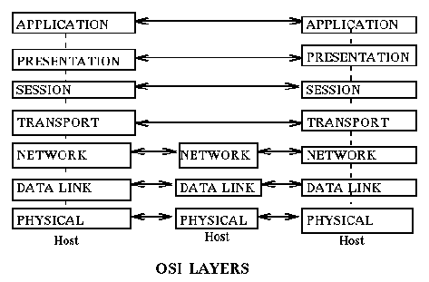
Stallings in his operating systems book [MacMillan 1992] has the
following simple characterization for the OSI Layers:
- Physical:
- Concerned with transmission of unstructured bit stream over physical link;
involves such parameters as signal voltage level and bit duration; deals
with mechanical, electrical, and procedural characteristics to establish,
maintain, and deactivate physical link.
- Data Link:
- Provides for the reliable transfer of data across the physical link;
sends blocks of data (frames) with the necessary synchronization, error
control, and flow control.
- Network:
- Provides upper layers with independence from the data transmission
and switching technologies used to connect systems; responsible for
establishing, maintaining, and terminating connections.
- Transport:
- Provides reliable, transparent transfer of data between end points;
provides end-to-end error recovery and flow control.
- Session:
- Provides the control structuure for communication between applications;
establishes, manages, and terminates connections (sessions) between
cooperating applications.
- Presentation:
- Performs transformations on data to provide a standardized application
interface and to provide common communication services; examples:
encryption, text compression, reformatting.
- Application:
- Provides services to users of the OSI environment; examples: transaction server, file transfer service, network management.
There is a fundamental difference between the lowest three levels
(the communication subnet) and the
top four levels of the OS architecture.
The bottom layers are between directly connected hosts
or involve all the hosts in a path from sender to receiver.
The top four layers are end-to-end protocols, that is, the communication
is stated in terms of only the original sender and the final destination,
independent of how many intermediate hosts are traversed.
Intermediate nodes do not participate at all in the processing of the
higher level protocols, to them it is data. [Think in terms of overhead:
In the source and target node protocols at all layers are processed.
In the intermediate nodes only protocols in the bottom three layers are
processed.]
This has a direct
impact on efficiency: for example, error checking in protocols at this level
is only done at the sender and receiver, not at the intermediate hosts.
Each message (or frame, or packet) consists of data being transmitted
plus information required by the protocol for addressing, error
detection, etc. This extra information appears as a header before that data
and (may be) a trailer after the data, i.e. the data is encapsulated
in the message. [Not all messages have both a header and a trailer.
Usually the trailer is not present.]
The message sent at layer i will be transmitted as data by the layer below it.
Assuming that the layer below can transmit this data as a single message
we will have the situation
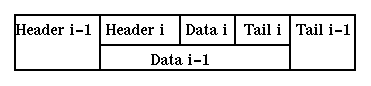
Note that the headers and tails consitute transmission overhead, reducing the
utilization of the bandwidth of the communication channel. Of course this
is only part of the communication overhead: retransmissions and
acknowledgements further reduce bandwidth.
Communication can be connection-oriented or connectionless.
In the former case a connection is established between the communicating
agents and on that connection messages are exchanged. In the latter instead
each message is treated as a free standing entity (datagram).
Related concepts at the communication level are circuit switched
and packet switched. In the former communication between interlocutors
always follows the same path [this may be "forever" or it may be only
for a single connection(virtual circuit)].
In the latter individual packets follow their own independent routes.
Another related concept is a session.
It consists of one or more connections.
For example, a program on machine A may be involved in communication
with a program on machine B, the connection drops due to communication
problems. When communication is reestablished the programs continue from
where they were in the session using a new connection. An example of a session
is the interactions during a remote procedure call. The requestor has to send
the request, possibly in multiple messages, the receiver collects them,
processes the request, then sends back the results. All in one session.
The transmission units at different layers may be of different maximum sizes.
We have here the same distinction that exists between "logical" and "physical"
records in file systems. One message at a layer may have to be fragmented over
multiple messages at a lower layer. [This is called
Fragmentation].
A layer may be able to accept messages of length N,
but the implementation of the layer in terms of a protocol
at the layer below may accept only messages of length M, with M < N.
Thus the original layer must be able to fragment the original
message into a number of messages at the lower level. These fragment may then
be sent across different routes and the receiver will have to worry about
missing fragments, incorrect received order, in
recombining them into the correct received message.
This problem occurs
in particular between the network layer (IP protocol) and the data link layer,
where the IP packet needs to be split into a number of fragments.
The opposite situation may also occur: At the data link layer with
ethernet we have messages of up to 1526 bytes. At the network layer
we may have a limit of 128 bytes. [Or the data link unit may be 53 bytes...]
Routing is the process by which a message moves from a
sender to a receiver across multiple intermediate hosts. It is a very complex
activity worth of its own separate course. Part of the complexity is that
we want to have a system that keeps on working while hosts and
links fail and come on line at their own pace. Routers are placed
between neighboring networks to decide which of the incoming packets should
be kept on the local network and which should me moved to the other
network. It is not an optimal process: packets keep a hop count that
is increment with each transfer. When it gets too big, as in a loop, the
packet is discarded.
A number of issues should be kept in mind when analysing a protocol
and its implementation. Among them:
- Framing: How do we recognise the beginning
and end of a message (or packet, or frame, or ..);
- Flow Control:
How do we make sure we don't send too much information to the receiver
so that it cannot handle it and has to "drop it on the floor";
- Multiplexing: How a single communication channel can be shared for
more than one conversation;
- Addressing: How do interlocutors address each other
[as we have already
seen, host interfaces are known by their IP address (a 32 bit integer);
unfortunately in ethernet the address understood by the hardware is the
Ethernet address (a 48 bit integer) of the connector; thus there is need
of a way to translate from IP to Ethernet addresses. In general, this
requires an address resolution protocol.
- Error Detection and Correction: what we do to detect if an error has
occurred in transmission and how to correct it.
Examples of protocols used at the various levels:
Application layer: telnet, ftp, finger, ..
Presentation layer: XDR
Session layer: RPC
Transport layer: TCP (connection oriented), UDP (connectionless)
Network layer: X.25 (connection oriented), IP (connectionless), ICMP (Internet Control Message
Protocol - connectionless)
Data link layer: HDLC, ethernet, ATM
Physical layer: RS-232-C, ethernet
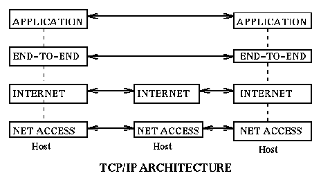
The TCP/IP architecture was developed mainly in the US. It is the one that
has the largest number of users. It represents pragmatic solutions to
problems as they arose. It involves only four layers:
The application layer (same as
in OSI), the end-to-end layer (TCP or UDP or ...), the internet layer
(IP, or ICMP, or ..),
and the net access layer (ethernet, or ATM, or PPP, or SLIP, or ....).
Internet addresses are used in the network layer (and above) protocols.
For example they are used in the IP protocol.
An internet integer is a 32-bit integer with the format
described in the following figure.
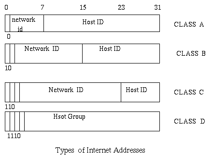
As you can see internet addresses usually have two parts, one identifying
a network, and the other identifying a computer on that network. The class D
is scarcely used. It is supposed to be for multicasting, i.e. for sending
messages to multiple users. The classes A, B, and C have repectively
a few networks,
each with many hosts, or a reasonable number of both, or a lot of networks
each with a few hosts.
To facilitate the use of internet addresses and the routing of messages
in a large local organization, it is possible to subdivide the host address,
say in the B class, into two parts, one for a subnetwork, the other for
the host. [You may want to use subnetworks to reduce traffic on the
subnetworks and to
facilitate their management.]
An internet address identifies a connection of a computer to a network.
Thus if a computer is connected to multiple networks it will have multiple
internet addresses.
Since an internet address is only 32 bits,
people are afraid that we may be
running out of such addresses and are working to create
a wider class of internet addresses.
Since it is hard to remember a 32 bit integer, people are accustomed to
represent it as a sequence of four numbers, one for each octet (byte).
For example snowhite is 155.247.190.1. And since also this is
hard to remember, people use names such as snowhite.cis.temple.edu
and require a name service to map one kind of identification into the other.
Internet addresses are not the only form of addresses used on the internet.
For example ethernet (physical and data link layer) uses 48 bit addresses
that are unique worldwide.
Hence a conversion problem arises, how to go from one kind of address
to the other and viceversa. Two protocols, ARP (Address Resolution Protocol)
and RARP (Reverse ARP), are used to this end.
The Internet Protocol (IP) is a connectionless protocol [messages are
sent individually, not after a connection has been established]
with "best-effort"
delivery [i.e. delivery will be tried but not guarantied]. Below is a
depiction of the IP's header.
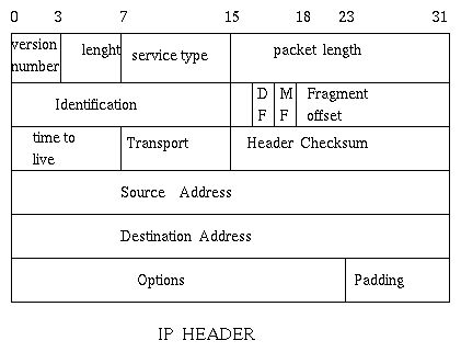
- Version Number:
- The version number of IP (currently, I think, is 4)
- Length:
- Since the header is of variable length (a minimum of five words,
the rest are optional),
it gives the length of the header as a number of 32 bit words.
- Type of Service:
- How urgent is this message: Precedence, normal delay, low delay, ..
The default is 0.
- Packet Length:
- The maximum length of an IP packet is 65,535 bytes, but usually less.
- Identification:
The identity of this packet. It is unique for a sending host.
- Flags:
- Two possibilities: DF (don't fragment) and MF (more fragments). It is used
to identify fragments in decomposed messages.
If the DF is set then we cannot fragment a long message coming from
the network layer [we have to discard it].
For example IP accepts messages of up to 64KB.
Ethernet instead supports messages of only up to 1526 bytes of data.
Thus an IP message will be fragmented before transmission using ether net
in the data link and physical layers. But this will take place only if
DF is not on.
- Fragment offset:
- Once an IP block splits, each fragment receives a copy of the IP
header and the fragment offset has to specify the relative position
of a fragment in the original message. Fragments are of lengths
that are multiples of 8 bytes [i.e. 1 means 8 bytes].
- Time to Live:
- Usually it is measured in "hops", i.e. the number of systems to traverse
at most before reaching the destination. A message is discarded if it
does more hops than the stated time-to-live of page.
- Transport Protocol:
- It identifies the protocol used at the next layer up [transport].
It usually is TCP or UDP.
- Header Checksum:
- The 1-complement of the 16 bit sum of the 16 bit words in the header.
- Source and Destination Addresses:
- Their internet addresses.
After the IP header there may be optional fields. Particularly
interesting is
the fact that a packet may contain directions on which path to follow,
request the nodes it goes though to inform the sender that they
have received the packet, and even to return a timestamp of when packet
was received. Thus one can follow a packet as it moves, and see at what
speed it goes.
Note that sufficient information is provided in IP packets to deal with
the problems of fragmentation [header length, packet lenght, offset
of fragment, if more fragments follow].
ICMP, which is also a network layer protocol, uses IP packets to transmit
control information. For example, it may inform that a host is unreacheable,
or that a node is unable to do buffering, or to request the local time of a node,
or to report such time, or to inform that a datagram was thrown outbecause of too many
hops.
The Transmission Control Protocol (TCP) is a connection oriented
[thus sender and receiver are as connected in a virtual circuit],
bidirectional, stream oriented [as opposite to message oriented,
i.e. users think in terms of sending and receiving a stream of
octets; the implementation will actually use messages, called segments.]
reliable transmission protocol at the transport layer.
The same format for the header is used in both directions in a
connection.
Here is a picture of the header of a segment and a description
of some of its fields.

- Source and Destination Ports:
- They are 16 bit numbers. A port number is local to a specific
host, i.e. different hosts have
65,535 different ports.
In unix /etc/services keeps a list of
specific uses for some of these ports.
For example, HTTP uses 80, Telnet
uses 23, FTP uses 21.
- Sequence and Acknowledgement Numbers:
- These numbers are local to a connection between two nodes, i.e.
they are unique during the life of message. The initial sequence number
is agreed between the sender and the receiver when the connection is set up.
For example, if two nodes A, B are communicating, then A as sender
may chose initially the number 200 and
B as sender may chose initially the number 500.
Then B will acknowledge messages relative to 200 and A will acknowledge
messages relative to 500. More on this later.
- Data Offset:
- Length of the TCP header, counted in 32-bit words.
- Flags:
- There are a variety. Among them:
- ACK: Confirms that the acknowledgement field is valid
- SYN: Request to setup a connection. It must be acknowledged.
- FIN: Request to shutdown. It must be acknowledged.
- Window Size:
- It specifies the size of the receiver's available buffer (called
window).
A way of sending reliably data is the following: each time a sender
sends
a message, it waits for confirmation, and only then sends the next message.
Unfortunately this can give rise to long transmission times.
An alternative is to send multiple messages
as long as one does not get too far ahead of the acknowledgements. This
common sense observation is the basis for the Sliding Window Algorithm.
It goes as follows. Each partner sets up and shares a window size.
Say A sets window to 100 and B to 200. Then A(B) feels free to send
up to 100 (200) octets without receiving acknowledgement. Then if A
has sent 80 octets and received acknowledgement for 20, it knows it can send
safely 40 more octets. And B reasons similarly.
Note that one packet can carry some data and simultaneously acknowledge
a previously received message.
Ethernet (standard IEEE 802.5) is the most commonly used protocol at the
physical, data link layer. It uses 48-bit addresses.
The Etherent packet has up to 1500 octets of
data. These are preceded by 20 for the IP header, 20 for the TCP/UDP
header, 6 for the sender address and 6 for receiver address, and an
initial 8 used for synchronization. The packed is followed by 4 OCTETS,
the CRC sum. Thus there is a 64 octet overhead for each message sent
with ethernet.
Many hosts can be on a LAN with ethernet. They all share the same
communication channel, thus multiple nodes may attemt to transmit
at the same time, with possible collisions. A protocol, CSMA/CD
(Carrier Sense, Multiple Access with Collision Detection), is used
to resolve the resulting problems.
The detailed knowledge of the TCP/IP architecture and of its implementations
is of interest mainly to specialists, people that will write themselves
implementations of new protocols, or upgrades of old protocols. Usually
system programmers will work above the Socket [or Stream] API.
For those interested in knowing more about TCP/IP and its
implementation there are a number of
wonderful books
by Stevens and others.
Though the OSI (and TCP/IP) architecture
arrives up to the "application layer", much
work these days is happening above that level, in what people call
middleware with things like the
Distributed Computing Environment (DCE)
and the
Common Object Request Broker Architecture(CORBA).
These systems help create an infrastructure to support the construction
and use of distributed applications.
A typical way in which people organize distributed applications is
represented by the Client-Server Model. In this model
a program at some node acts as a Server which provides
some Service, things like a Name Service, a File Service,
a Data Base Service, etc. The Client sends requests to the Server and receives
replies from it. The Server can be Stateful or
Stateless, i.e. may remember information across different
requests from the same client. The Server can be iterative
or concurrent. In the former case it processes one request
at a time, in the latter it will fork a separate process (or create a separate
thread) to handle each requests. Also the Client could be
iterative or concurrent, depending if
it makes requests to different servers sequentially or concurrently. The
traditional way of interaction from the client to the server is with
Remote Procedure Calls (RPC).
Note that the way we interact with an object, by calling one of its methods,
is a typical client-server interaction, where the object is the server.
Thus distributed objects fit within the client-server
architecture. Objects, at different times, may play the role of server
to the other.
In the Client-Server Architecture the initiative lays always with the client.
The server only responds to requests [the requests are pulled
from the server].
A Peer-to-Peer Architecture instead emphasizes that the
interaction initiative may lay with any object.
These days much of the development in distributed applications takes the
form of
intranets. An intranet is a distributed system
providing access to the information systems of an enterprise through the
use of internet, and more specifically web,
technology using usually web browsers. Central issues are:
- What services are provided [e-mail, group cooperation tools,
access to legacy information systems, access to data bases, workflow
support, ..].
- How to access in a safe manner information through passwords,
encryption, etc. Different people in an organisation need to receive
different rights and the size of the entities protected may be fine. Rights
must be safely and conveniently granted and revoked.
- How to access from a web server traditional SQL databases.
- How to limit the cost of development and
maintenance of the information systems and the cost of service.
Companies such as Microsoft, Netscape, Oracle, Sun are most active in
this field. Languages, standards, and systems such as Visual Basic, Java,
JavaScript, VBScript, CGI, Perl, HTTP, HTML, Beans, ... are being employed.
The creation of the infrastructure to support intranets is highly technical.
The implementation of specific intranets using existing tools is
fairly low tech.
ingargiola.cis.temple.edu